Complete QAM and OFDM Transmitter/Reciever
While the test blocks for the DSP board were being developed, work was also being done on integrating the OFDM and QAM designs. Figure 1 shows the overall block diagram for the complete radio. This radio design does not take into account synchronization.

Figure 1 - Complete Radio with OFDM and QAM, no synchronization
The test data comes from the “Sradio Test IN” block. This block, is the test interface that was developed earlier. It will output data blocks in a 256 byte column arrary. When run in Simulink, the block outputs an initial frame of all zeros then a frame containing the string “Test string.” padded by zeros up to the 256 fame size, and then zeros until the simulation is stopped. The frames are output once per second.
The data then gets QAM encoded, OFDM modulated, interpolated and mixed to a higher frequency of 131.072 KHz. After this it is sent through a channel model (which has no effect for now), demodulated, decimated, OFDM demodulated, QAM decoded and then saved to the Matlab workspace where it can be examined. This design has many different sampling rates which needed to be tracked carefully to ensure a working simulation.
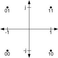
In the QAM modulation block, each byte of the ASCII data gets separated into groups of two bits. Each bit is then mapped onto a 4 level QAM constellation shown in figure 2.

Figure 2 Four Level QAM/QPSK constellation
This constellation was chosen to ease decoding. The MSB is 0 when the real part is negative and 1 when the real part is positive. The LSB is 0 when the imaginary part is negative and 1 when positive.
The QAM data stream needs to be mapped to appropiate OFDM subcarriers. A 64 point IFFT/FFT was chosen for this project because that is what is used in the 802.11a standard. Figure 3 shows the OFDM subcarriers as given by the 802.11a standard.

Figure 3 - 802.11a OFDM subcarriers
The subcarrier at 0 or DC is not used so problems with the RF circuitry and ADCs will not occur. Eleven subcarriers are not used on either end of the spectrum to make it practical to filter when upsampling. Pilots are also inserted at carriers -21,-7, 7, and 21 to help with synchronization. Since just 4 QAM symbols are being transmitted at once, only carriers 1,2,3, and 4 will be used at this time. This is shown in figure 4.

Figure 4 - Project current OFDM subcarrier map
Karl on 02.14.06 @ 04:27 PM CST [link] [No Comments]
