[Previous entry: "Thoughts on system block diagram and flow of project"] [Next entry: "RTDX Interfacing and Testing II"]
01/11/2006: "RTDX Interfacing and Testing I"
The RTDX interface in Simulink was investigated to verify the transfer of data to and from the DSP board when testing the software radio. RTDX is a way to programmatically send and receive data to and from the TI 6713DSK board through code composer studio. Although the interface will not work in a production environment, it is an excellent way to send data to the DSK board for testing.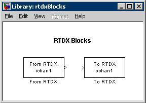
Figure 1 - RTDX Blocks in simulink
The From RTDX block receives data from the host PC and transmits that data to the DSK board. The To RTDX block transmits data from the DSK board to the Host PC.
As a starting point for testing, the model in figure 2 was created.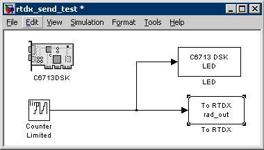
Figure 2 - Test model for RTDX data tranmission from DSK to PC
The model counts from 0 15, incrementing every 1 second and transmits this to the RTDX channel. This value is also sent to the LEDs so that there is a visual indicator on the board that it is still running the program.
Communication on the host side was programmed in Matlab. The Code Composer Studio link for Matlab provides functions for interfacing with RTDX.
When receiving an RTDX message in matbab, there are 3 things one needs to first do:
1. Enable RTDX overall
2. Open the specific RTDX channel.
3. Enable the specific RTDX channel.
Once this takes place, the board will begin to transmit the data to code composer studio. When the connection is not enabled, the messages are lost. The message is then read with the readmsg function. After the data is taken in, the channel is then disabled, closed, and rtdx itself is disabled.