Software-defined Radio
using Xilinx
System Tools (Xilinx)
The entire QPSK communication system is
created in the Simulink environment of MathWorks©. Simulink is a
module based method for simulating and implementing an engineering
system. The module libraries provide a broad range of modules for
different tasks such as mathematical operations, signal processing
algorithms, error calculations, filter design etc. Compounding
various blocks from the communication and signal processing block
sets into a pseudo-flowchart creates a fully functional system,
without the traditional method of line by line coding.
The Xilinx system generator is a tool box running in Simluink
environment for FPGA hardware design.
It provides integrated design flow using hardware description
language synthesis, core libraries, and FPGA implementation tools.
Due to the discrete nature of FPGA architecture, data values are
represented in a fixed-point binary format as opposed to a
floating-point representation. The Xilinx block set includes a large
number of functions which require fixed point arithmetic. Therefore,
memory management and proper data representation require special
attention, unlike floating-point signal processing.
The Xilinx system generator blockset is accessible in the
Simulink library browser, and elements can be freely combined with
other Simulink elements.
It allows choosing the target FPGA device, system clock
period, and other implementation options.
It provides an efficient way to simulate and verify the
design from system specification level to hardware realization
level.
Fixed-point representation is essentially a method of representing a
value with a designated number of bits and precision.
For example, a data type, UFix_14_12, stands for a
14-bit unsigned fixed-point number with 2 bits of integer data and
12 bits of decimal precision.
In digital systems, selecting a proper fixed-point
representation is crucial for functionality and progress. Improper
representation can lead to loss of precision, overflows, sign
errors, and other discontinuities throughout the rest of the system.
In the QPSK communication system, the transmitted data has the
representation of Fix_32_31, describing a 32 bit signed
number, with the most significant bit being the sign bit, and the
remaining 31 bits defining the decimal precision. The range of the
signed value is from -1 to 1.
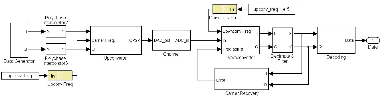
The overall system diagram of the QPSK system is shown
here. It includes the
following function blocks: data generator, interpolator, upconverter,
channel, downconverter, decimator, carrier recovery, and decoding.
For more information regarding the methods used in the construction
of the Simulink block diagram follow the links for
data generation,
raised-cosine filter,
phase-locked loop, and
differential coding.