The Inductrack theory can be explained by using control theory. The system can be
modeled by an resistor and an inductor (RL) in series. The sinusoidal voltage source would be the
induced voltage created by moving the Halbach array over the track. Frequency changes correlate
to changes in the velocity of the Halbach array. Low frequencies are slow velocites, and high frequencies
are fast velocities. The RL circuit is shown in figure 1.

Figure 1 - Modeled Inductrack Circuit
Using ORCAD PSPICE, the circuit is simulated with arbitrary values placed as components.
The Bode plots are shown in figure 2.
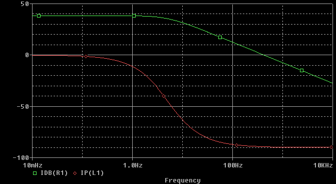
Figure 2 - Simulated RL Circuit Bode Plot
The transfer function for the current is shown by
I(s)/V(s) = (1/L)/[(R/L) + s]
Using this transfer fucntion, the Bode plots are shown in figure 3 by using MATLAB.
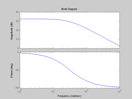
Figure 3 - Plotted RL Circuit Bode Plot
A pole is located at R/L. Poles determine the frequency where the phase decreases. This means that the
greater the R/L pole, the greater the velocity for levitation, because the train begins to convert drag forces to levitation forces as the
induced current's phase begins to lag. Thus, the lift to drag ratio can be shown by
Lift/Drag = omeg*L/R
The ideal goal is to obtain the greatest lift to drag ratio.