Functional
Description of Components:
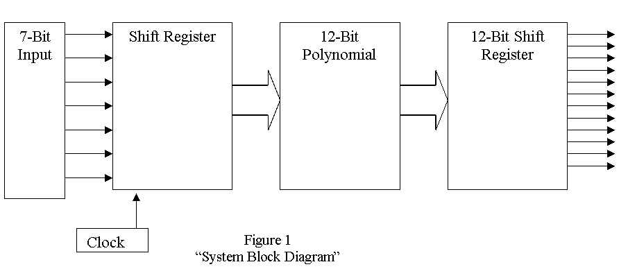
Input: The input is
given as a 7 bit parallel input. Four
bits make up the code word and three bits are for parity checking.
7-Bit Shift Register: The
data is put into a shift register to create the binary polynomial for
manipulation by the multiplier.
Multiplier: Takes a
hardwired, permanent encryption polynomial, G(x), and multiplies with the input
polynomial, Y(x). This creates the
12 bit encrypted polynomial. This
is accomplished with logic gates and
shift registers.
12-Bit Shift Register: Takes
the output and from the multiplier and prepares it for parallel output from the
chip.
Clock: Will control
the speed at which the shift registers operate.