 .
.
Frequency Measurement Methods:
A. National Semiconductor Corporation: LM2907/LM2917
General Description:
The National Semiconductor Corporation LM2907, LM2917 series are monolithic frequency to voltage converters with a high gain op amp/comparator designed to operate a relay, lamp, or other load when the input frequency reaches or exceeds a selected rate. The tachometer uses a charge pump technique and offers frequency doubling for low ripple, full input protection in two versions and its output swings to ground for a zero frequency input.
Advantages:
Applications Information:
The input stage is followed by a charge pump where the input frequency is converted to a dc voltage. This requires one timing capacitor, one output resistor, and an integrating or filter capacitor. When the input stage changes state (due to a suitable zero crossing or differential voltage on the input) the timing capacitor is either charged or discharged linearly between two voltages whose difference is VCC/2. Then in one half cycle of the input frequency or a time equal to 1/2 fIN the change in charge on the timing capacitor is equal to VCC/2 * C1. The average amount of current pumped into or out of the capacitor then is:
ic(AVG) = C1 * (VCC/2) * (2fIN) = VCC * fIN * C1
The output circuit mirrors this current very accurately into the load resistor R1, connected to ground, such that if the pulses of current are integrated with a filter capacitor, then VO = ic * R1, and the total conversion equation becomes:
VO = VCC * fIN * C1 * R1 * K
As a final consideration, the maximum attainable input frequency is determined by Vcc,C1 and I2:
f = I2 / (C1 * Vcc)
B. Fluke 1910A/1911A Counter
Frequency Mode:
Information is from the instruction manual. For the frequency mode of operation the signal to be measured is applied and transformed into standard ECL levels for application to the main gate. The ECL level signal will be passed to the high speed dividers for a time interval determined by the selected range. The high speed dividers then divide the unknown input to obtain the first and second digit information. The high speed dividers are necessary because the maximum toggle speed of the counters is 2 MHz. The digit information is strobed into the latches by a memory update signal generated by the controller. The controller simultaneously supplies a pulse with the digit strobe to position the decimal and to light the appropriate annunciators. The latches (within accumulator) will hold and present the entire digit information to the display on a common data bus. The accumulator also generates the strobe cycle to enable the correct LED to light. Each LED is strobed individually for a period of 90 usecs. This individual strobe scheme increases the LED life and decreases the energy consumption, persistence of the eye eliminates any flicker.
C. Fluke 45 Dual Display Multimeter
Frequency Measurement:
Information is from the Fluke 45 Dual Display Multimeter manual. Frequency measurements from 5 Hz to > 1 MHz are automatically ranged so that a frequency measurement is always displayed with maximum resolution. The rate at which frequency measurements are taken is a factor of the frequency being measured. Frequency measurements are always taken using the ac input circuitry of the meter.
Music Catalog Search:
In order to conduct this search, the primary source was the online catalog for International Music Suppliers. Several tuners with different features and price ranges were available to view.
The cheapest tuner available in the catalog was a Korg CA-10 for $21.50. Features include tuning 7 octaves and a manual note selection mode. This tuner does not have the same extent of features as that being designed for the senior project. It is not capable of sounding notes or displaying them to the user, but only has a simple analog meter for pitch indication.
One of the more expensive models seen in the catalog was the Peterson Strobe Tuner, Model 590. Features for this higher end model include audio and visual tuning, with a visual range of 8 octaves. The audio range is 5 octaves, and the tuner comes with a case. Model 590 is priced at $670. Other features which further set it apart from the more moderately priced tuners were not evident. Higher pricing is most likely a by-product of better quality and precision within the tuner, as well as the expanded functionality mentioned above.
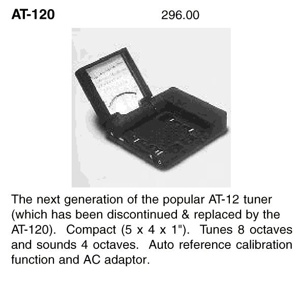
Korg produces a AT-120 model which has the most similar functionality
to the senior project tuner. The cost for the AT-120 is $296.
It includes a wide tuning range from C0-E8, auto and manual modes, cent
and Hz tuning (ranging from 65.4-1,976 Hz), and auto reference calibration.
The auto reference calibration of this tuner stands out in that it has
a wider range of calibration, 1 Hz steps from 390 Hz to 470 Hz. The
range from 390 Hz to 470 Hz is surrounding the note "A" at 440 Hz.
In some cases, the musician may not wish to tune their instrument around
the fundamental pitch of A = 440 Hz. If time permits, a calibration
function will be added to the senior project auto-chromatic tuner.
Another tuner which appeared to be similar was the Seiko ST1200. The ST1200 has an 8+ octave tuning range along with a 4 octave pitch sounding range. This tuner stands out in that the note, octave, and pitch are shown on a large display. The cost for the model is $259.50. The advanced display apparently sets this tuner apart from others on the market.
Tuner Manual:
The tuner used by Dr. Vroman in Dingeldine to tune the bands is a Korg AT-12 Auto- Chromatic Tuner. A manual came with the tuner specifying the features and functionality of the device.
Features:
Basic Functions:
Many of the features of the Korg AT-12 are comparable to those
being designed for in the senior project. This tuner contains all
of the modes desired for the auto-chromatic tuner being created.
The functionality is expanded with the various input and output jacks.
This tuner has a good analog tuning meter, but does not have the LED/LCD
display functionality of the senior project design. Note: The
AT-120 is an extended model of the AT-12 after it was discontinued, see
below for a brief description of the AT-120
.