Main
Page
Auto-Chromatic Instrument Tuner
System Level Block Diagram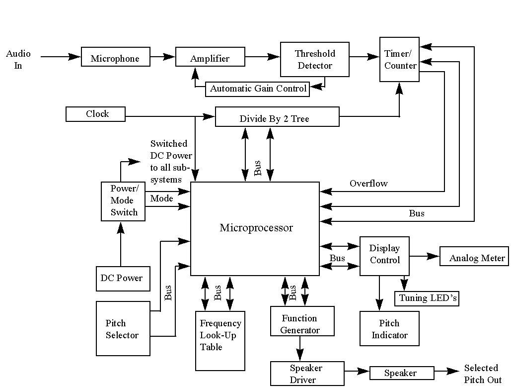
1.Microphone:
-
Inputs: Physical audio signals from environment
-
Outputs: Electrical representation of audio signals to the Amplifier
-
Functional Description: Picks up an acoustic signal and converts it to
an electrical signals
-
Relation to Overall System: Main system input - entry point for unknown
played pitch
2.Amplifier:
-
Inputs: Electrical audio signal from Microphone and Automatic gain
control
-
Outputs: Amplified audio signals to Threshold Detector
-
Functional Description: Increases the amplitude of the electrical audio
signals to a more easily processed level
-
Relation to Overall System: Matching network and gain block between 1)
Microphone and 3) Threshold Detector
3.Threshold Detector:
-
Inputs: Amplified audio signal from the Amplifier
-
Outputs: TTL level pulses with rising and falling edges corresponding to
fundamental period of input signal to the Timer/Counter and Automatic gain
control signal
-
Functional Description: Converts input signal to fundamental frequency
information
-
Relation to Overall System: Extracts the fundamental frequency from a complex
audio waveform
4. Automatic Gain Control
-
Inputs: Data from the Threshold Detector
-
Outputs: Takes information from the Threshold Detector and feeds back to
the amplifier
-
Functional Description: Helps regulate the gain and provides more stability
in the system
-
Relation to Overall System: Feeds back the signal from the Threshold
Detector to the Amplifier
5.Timer/Counter:
TTL
pulses from Threshold Detector
Count Clock from Divide By 2 Tree
Overflow
to Microprocessor
Fundamental Count to Microprocessor
-
Functional Description: Counts the time between fundamental periods, triggers
overflow if count overflows
-
Relation to Overall System: Quantitatively measures the period of the fundamental
frequency of the original signal
6.Clock:
-
Inputs: None
-
Outputs: Main Clock to Divide By 2 Tree and Microprocessor
-
Functional Description: Provides the clock signal for all components that
require one
-
Relation to Overall System: Provides required timing information so that
the played pitches can be analyzed with respect to a consistent reference;
synchronizes microprocessor and logic timing
7. Divide By 2 Tree:
-
Inputs: Main timing signal from Clock
-
Outputs: Count Clock to Timer/Counter
-
I/O: Divide by 2n control to/from Microprocessor
-
Functional Description: Divides the Main Clock by the nth power of 2 to
give Count Clock.
-
Relation to Overall System: Permits measurement of a wide variety of frequencies
with maximum resolution, since pitches are based on octaves, which is a
base 2 system (e.g. all "C"s have frequencies which are related by multiplying
or dividing by a power of 2
8. Power / Mode Switch:
Physical
Switch Position from User
DC Power from DC Power Supply
Switched
DC power to all subsystems.
Mode to Microprocessor
-
Functional Description: Controls power to the system and selects the operating
mode
-
Relation to Overall System: Allows the user to turn the system on and off
and select the operating mode
9. DC Power:
-
Inputs: DC Power Source
-
Outputs: DC Power to Power / Mode Switch
-
Functional Description: Provides the electrical power for the entire system
-
Relation to Overall System: Connection for battery, power supply, etc.
to power the system
10. Pitch Selector:
-
Inputs: Button pushes by user
-
Outputs: Pulses from switches
-
Functional Description: Allows the user to select a pitch from C0 to B9
(C in the 0th octave to B in the 9th octave)
-
Relation to Overall System: Allows to the user to select pitches for Manual
Tuning and Audible Reference Pitch modes.
11. Frequency Look-Up Table:
-
I/O: Frequency Reference Data to/from Microprocessor
-
Functional Description: Contains reference data for frequencies of one
full octave
-
Relation to Overall System: Provides the system with a reference to which
it can compare the frequency of the played pitch; only one octave is needed
since the frequencies can simply be multiplied or divided by powers of
two (by simple binary left and right shifts) to get the other octaves
12. Function Generator:
-
I/O: Function Generator Control to/from Microprocessor
-
Outputs: Electrical Audio Output Waveform to Speaker Driver
-
Functional Description: Generates audio waveforms
-
Relation to Overall System: Generates waveforms for selected pitches in
Audible Reference Pitch mode
13. Speaker Driver:
-
Inputs: Electrical Audio Output Waveform from Function Generator
-
Outputs: Speaker Audio Signal to Speaker
-
Functional Description: Amplifies the output audio signal to drive a speaker
-
Relation to Overall System: Provides the necessary current and voltage
levels to allow the speaker to produce selected pitched audibly in Audible
Reference Pitch mode
14. Speaker:
-
Inputs: Speaker Audio Signal from Speaker Driver
-
Outputs: Acoustic Signal to environment
-
Functional Description: Converts electrical energy into acoustic energy
-
Relation to Overall System: Allows selected pitches to be heard
15. Display Control:
-
I/O: Display Control to/from Microprocessor
-
Outputs:
Analog Tuning Error Signal to Analog Meter
Digital Tuning Error Signal to Tuning LEDs
Pitch Display Data to Pitch Indicator
-
Functional Description: Controls all of the display elements based on information
from the Microprocessor.
-
Relation to Overall System: Controls devices which display necessary information
to the user
16. LCD/LED Bar Indicator
-
Inputs: Analog and Digital Tuning Error Signal from Display Control
-
Outputs: Visual indicator (LEDs and meter) to User
-
Functional Description: Lights LCD/LEDs based on tuning error.
-
Relation to Overall System: Gives the user visible feedback on the tuning
of the played pitch
17. Pitch Indicator:
-
Inputs: Pitch Display Data from Display Control
-
Outputs: Visual indicator (3 seven segment LEDs) to User
-
Functional Description: Displays characters on the seven segment displays
indicating a pitch
-
Relation to Overall System: Tells the user what pitch is being tuned or
played on the speaker
18. Microprocessor:
Overflow from Timer/Counter
Main Clock from Clock
Mode from Mode/Power Switch
Selected Pitch from Pitch Selector
Divide By 2n Control to/from Divide By 2 Tree
Frequency Reference Data to/from Frequency Look-Up Table
Function Generator Control to/from Function Generator
Display Control to/from Display Control
-
Functional Description: Executes code (see flow chart) which controls subsystems,
reads inputs, performs all calculations, controls outputs, etc
-
Relation to Overall System: Heart of the system; determines all operating
characteristics of the system according to user input.
Main Page