Project Weekly Progress Report
Project Title:
Microcontroller Implementation of a Small Robot Arm Controller
Week of: March 28th, 2000
Engineers:
Megan Bern and Ritesh Patel
Advisors Signature: _________________
Grade: _______
=================================================================
Objective:
For the week of March 28th, 2000, the first objective was
to design a filter to place at the output of the joystick. The second objective
is to continue the menu system.
Progress:
The pole of the low-pass filter shown at the output of the step block
in Figure 1 was experimentally chosen using simulink. Various values for
the pole were entered into the simulation and the output of the controller
(Scope) and the response before the D/A converter (Scope1) were evaluated.
The results of Scope and Scope1 were looked at before the low-pass filter
was added to the system in simulation. Scope and Scope1 are shown in Figures
2 and 3. As you can see from the results, Scope1s output hits the rail
before it settles to 2V. This is something we would like to fix.
The value that we decided to use for the pole was 10 rad/sec. The simulation
results with the low-pass filter added in are shown in Figures 4 and 5.
The results for Scope1 are much better with the low-pass filter inserted
in the simulation. The output is within a safe distance from the rail.
The value 10 rad/sec will be the value of the pole implemented in hardware.
Without the filter, the control system operation would be nonlinear and
unpredictable.
Figure 1:
Block Diagram for P Controller
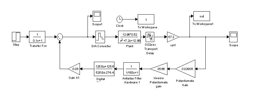
Figure 2:
Scope Results without Low-pass Filter

Figure 3:
Scope1 Results without Low-pass Filter

Figure 4:
Scope Results with Low-pass Filter

Figure 5:
Scope1 Results with Low-pass Filter

The low-pass filter will be represented in hardware as shown in Figure
6. The low-pass filter is represented by (1).
Figure 6:
Schematic for Joystick Filter

 where 1/RC=pole value (1)
Figure 6 shows the values for R and C which are: R=1MW
and C=10m F. These values for R and C give the
10 rad/sec pole that is needed. We measured the components chosen for the
hardware using a Hewlett Packard 4261A LCR Meter. The results for the measurements
are: R=1.0038MW and C=10.44m
F @ 120Hz.
where 1/RC=pole value (1)
Figure 6 shows the values for R and C which are: R=1MW
and C=10m F. These values for R and C give the
10 rad/sec pole that is needed. We measured the components chosen for the
hardware using a Hewlett Packard 4261A LCR Meter. The results for the measurements
are: R=1.0038MW and C=10.44m
F @ 120Hz.
These values were than entered into Figure 1 and simulated using Simulink.
The results are shown in Figures 7 and 8. As you can see there is not a
significant difference in Scope or Scope1, so these component values are
going to be used.
Figure 7:
Scope Results with Measured Component Values

Figure 8:
Scope1 Results with Measured Component Values

The schematic shown in Figure 6 was then built. We then ran the previously
written code to test our joystick filter. The robot are was not working
properly. We found that the breadboard we were using for our hardware was
bad. We then decided to rebuild all of our hardware on a different breadboard.
After the hardware was transferred to another breadboard, the software
was ran again. The robot arm was spinning around in a 360°
circle. This means that our P Controller block diagram shown in Figure
1 is not an accurate design. Several hours were spent on this problem and
a conclusion has not been reached on how to correct it.
The menu system was the next item of the week. The input the system
could either be a joystick or a choice of a certain degree that the user
wants the robot arm to move to entered by the keypad. Since we only received
a 60° position swing using the joystick,
which was based on a 0V-5V range, that will be all we can offer to the
user from the keypad. The theory for accepting the desired position from
the keypad and moving the arm to that position has not been developed yet.
Conclusion:
The filter for the joystick was simulated and built. It was not tested
due to the problem with the P controller. The menu system is still being
worked on. We are now behind schedule. Feedforward design will be taken
out of the schedule due to the delay with the menu system and the P controller.
The schedule for weeks 10-12 is shown below.
Schedule for Weeks 10-12
Week 10 P Controller/menu system
Week 11 Modify/add to Menus/Testing
Week 12 Proportional-derivative Controller
home