Introduction
This project is a laser shootout game. The original idea is attributed to Christopher Rockhold, who has a 1988 patent for a game mimicking fictitious Old West gunfighting. In his "electronic shootout game" and in this project, two players stand across from one another, waiting for a signal to draw their weapons and start firing. The weapons use laser transmitters and receivers for the shots, and players wear reflective vests to reflect a weaponís laser beam back at the weapon to be detected. Each player also has access to a display board, which provides them with game information. The weapons use wireless technology to communicate to the display boards, and the displays use serial data transmission to communicate with a central controller unit.
This project involves the use of several technologies. Laser data transmission and reception is a central feature. Communication between microprocessors using Radio Frequency (RF) and a serial interface will also be used. Finally, the many different hardware and software systems will have to be integrated in order to make the system work properly. For simplicity, the project is divided into three main subsystems: the central controller (C.C.), the display boards, and the weapons. In the following paper, each of these subsystems will be described in detail.
Previous Project Work
Two senior project groups have worked on this system before this year. In 1997, David Grimm and Scarlet Halabi worked on an electronic shootout game, focusing on hardware development. They designed and built a working laser transmitter and receiver. The receiver was unreliable, but functional. The next year, in 1998, Nazry Jaafar, Azrin Johari, and Emelia Malek also worked on the same project. They improved the receiver design, although it still did not work at high frequencies. They also developed functional software for the weapon system, and were successful in getting microprocessors to communicate serially. It is hoped that these accomplishments can be built on and extended this year.
Patents, Standards, and References Research
In preparing for this project, searches were made for relevant patents, standards, and references. The following results were found.
There are many patents held for all kinds of laser guns or light guns. Most of these are for toys, but some "laser tag" systems are somewhat similar to this project. There is also the patent held by Rockhold, for his electronic shootout game, which is the original predecessor to this project.
Many standards could also apply to this project. There are several standards for the safe use of lasers. There are also regulations on all kinds of electronic systems and electrical toys. Since this project will use lasers, microprocessors, and qualify as a game, all of these may be relevant.
Several references were also found that could help in this projectís development. For example, a few references were found related to data transmission and reception using lasers.
Detailed Project Description
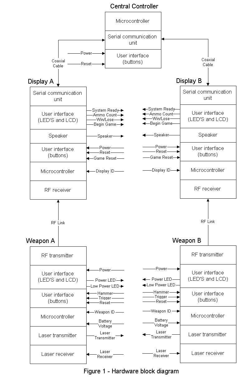
Figure 1 shows an overall block diagram of the project, including the three main subsystems (central controller, display boards, weapons). The following sections describe the subsystems in detail, looking as their hardware and software.
Hardware
The system consists of one central controller, and a weapon and display board for each player. Figure 1 gives an overall block diagram of the main hardware components and its subsystems.
Central Controller
The central controller starts the games and decides which player wins the game. The central controller consists of a microcontroller, a serial communication unit, and a user interface. The user interfaces are a power and a reset button. The serial communication unit allows the microcontroller to talk to the display units.
Display Boards
The displays are small scoreboards located near each player. They communicate with the weapons and the central controller, and display game information (See tables 1-3). The display consists of a serial communication unit, a user interface, a speaker, a microcontroller, and an RF receiver. The serial communication unit allows communication between the microcontroller in the display and the microcontroller in the central controller. The RF receiver allows the weapon to talk to the display board. The user interface is several LEDís and LCDís that display game information. It displays a light if the system is ready. The LCD displays the ammo count and a countdown to begin the game. The LCD also displays the result of the game when it is over. The speaker makes a noise when the gun is fired. There are also several buttons in the user interface for power and reset. When the system is set up, the Display ID may also be set to match the Weapon ID of a weapon, so the wireless communication may be synchronized.
Weapons
The weapon is a portable, wireless unit. It consists of a RF transmitter, user interface, microcontroller, laser transmitter, and laser receiver. The RF transmitter sends information to the display. The user interface has several LEDís that represent battery power, low power, and out of ammo. The user interface on the weapon also has buttons for the hammer, trigger, and weapon reset. The laser transmitter sends out the laser when the microcontroller tells it to. An opponent is hit if the laser reflects off of their vest and returns to the firing weapon. The laser receiver detects the reflected laser and informs the microprocessor to indicate a hit. Each weaponís ID should be set to match a displayís ID, so that when it sends data, the correct display will receive it.
Numerical Specifications
Tables 1-3 give a description of the system inputs and outputs. Tables 4-6 give estimated numerical specifications for these signals.
Software
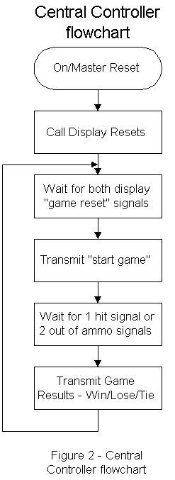
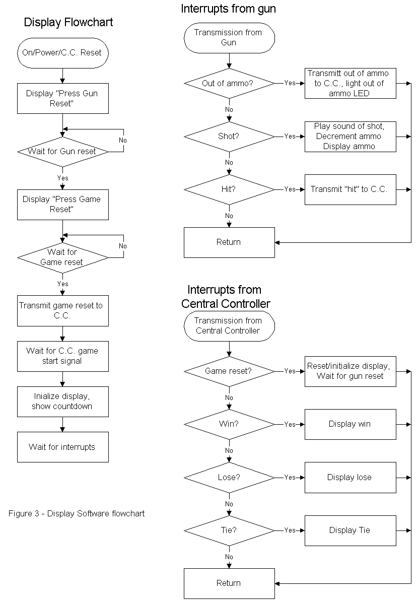
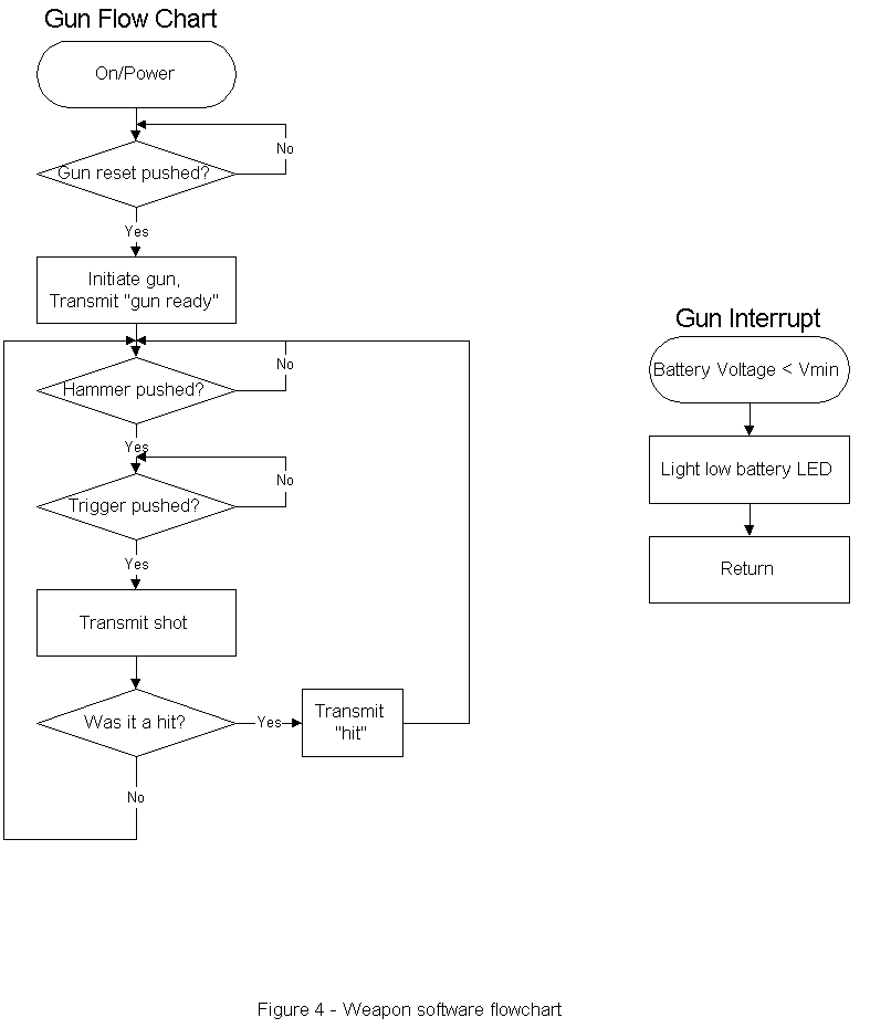
Figures 2 through 4 show the proposed software flowcharts for this project. There are three separate algorithms, one for each microcontroller-driven component: the central controller, the display boards, and the players' weapons.
Central Controller
Figure 2 shows the software flowchart for the central controller. This is a simple algorithm: When the system is turned on or the master reset button is pushed, the processor will first initialize itself. It will then transmit a signal to the display boards, telling them to reset, in preparation for a game. The processor will then wait for the displays to respond with ready signals. After both display boards are ready, it will broadcast a "game start" signal, and let the other microcontrollers run the game. The central controller then waits for one "hit" signal (a game victory) or two "out of ammo" signals (a tie) from the display boards. When one of these situations happen, the central controller broadcasts the game results, and waits for the next game.
Display Boards
The algorithm for the display board is shown in figure 3. When a display board is turned on, or when it receives a "reset" signal from the central controller, it will power-up and initialize, clearing the LCD display. It will then wait for a "game start" signal, which is generated by a player pushing a button on the display board. It will also wait for a "gun ready" signal from the player's weapon, to ensure that the wireless communication link works. After that is received, the display board transmits a ready signal to the central controller, and when the central controller responds with its "game start" signal, the game begins, and the display will show a countdown for each player to draw their weapon.
At this point, the display board's microcontroller waits for further communications from the weapon or central controller. As the interrupt-handler flowcharts show, if a signal is received from the gun (shot, hit, or out of ammo), the processor will take the appropriate action. Also, when a signal is received from the central controller (Game reset, win, loss, or tie), the processor will perform the necessary end-of-game actions and return to waiting for a new game.
Weapons
Figure 4 shows the flowchart for each weapon's microcontroller. Because the gun has a wireless transmitter but not a receiver, it operates in isolation and transmits signals that the display board will analyze for the game. Each signal is prefaced by the weaponís Weapon ID (set to match a displayís ID) so that the matching display will know itís being addressed. When the weapon is turned on, it initializes and waits for the "gun reset" button to be pushed. When this occurs the weapon transmits a "gun ready" signal so the display board can verify the wireless transmission. Then the gun is ready to fire. When the hammer is "pulled" and the trigger pressed, a "shot" signal is sent. The microcontroller then uses the laser to transmit a pulse. If the pulse is reflected and received properly, a hit is scored, and a "hit" signal is sent. Then the microcontroller returns to waiting for another trigger-pull or reset. There is also an interrupt handler in each weapon to light a "low power" LED and warn the display if the battery voltage falls below a certain minimum level.
Input and Output Descriptions
Table 1- Description of Inputs and Outputs
|
Signal Name |
Input/Output |
Description |
|
Central Controller |
||
|
Power |
Input |
Power provided by a wall outlet |
|
Reset Central Controller |
Input |
Button pushed to reset the entire game |
|
Displays |
||
|
Power |
Input |
Power provided by a wall outlet |
|
Disaply ID |
Input |
ID Number to match Display and Weapon |
|
Begin Game |
Output |
Row of LEDís counts down to game start |
|
Speaker |
Output |
Makes sound effects for gun noises |
|
Ammo Count |
Output |
Displays remaining ammo count on LCD |
|
Win/Lose |
Output |
Displays outcome of game on LCD |
|
Weapon Ready |
Output |
LED lights up from when the weapon is reset until the game is over |
|
Weapons |
||
|
Battery Power |
Input |
Power provided by a battery |
|
Reset |
Input |
Button pushed to reset gun in order to start game |
|
Hammer |
Input |
Button pushed to cock the gun |
|
Trigger |
Input |
Button pushed to fire the gun |
|
Laser Receiver |
Input |
Sensor used to detect reflected laser beam |
|
Weapon ID |
Input |
ID Number to match Display and Weapon |
|
Laser Transmitter |
Output |
Emits laser beam when the gun is fired |
|
Low Power |
Output |
LED lights up when battery voltage is low |
|
Power |
Output |
LED lights up when gun is on |
Table 2 - Coaxial Cable Signal Description
|
Signal Name |
Direction |
Description |
|
Game Reset |
From Central Controller to Displays |
Resets entire system |
|
Game Start |
From C.C. to Displays |
Starts countdown to beginning of game |
|
Game Winner |
From C.C. to Displays |
Reports game outcome |
|
Display/Gun Ready |
From Display to C.C. |
Tells C.C. that display and weapon are ready |
|
Target Hit |
From Display to C.C. |
Tells C.C. that player hit opponent |
|
Weapon Out of Ammo |
From Display to C.C. |
Tells C.C. that player has shot all six rounds |
Table 3 - RF Link Signal Description
|
Signal Name |
Direction |
Description |
|
Weapon Reset |
From Weapon to Display |
Tells display that weapon and player are ready to start a game |
|
Weapon Fire |
From Weapon to Display |
Tells display to decrease ammo count and make gunfire sound effect |
|
Target Hit |
From Weapon to Display |
Tells display that player hit opponent |
|
Low Power |
From Weapon to Display |
Tells display that weapon battery voltage low |
Numerical Specifications
Table 4 - Inputs and Outputs
|
Signal Name |
Input/Output |
Specification |
|
Central Processor |
||
|
Power |
Input |
+5V |
|
Reset Central Processor |
Input |
TTL levels |
|
Displays |
||
|
Power |
Input |
+5V |
|
Begin Game |
Output |
LED |
|
Speaker |
Output |
A large dB level above ambient room noise |
|
Ammo Count |
Output |
Display |
|
Win/Lose |
Output |
Display |
|
Weapon Ready |
Output |
LED |
|
Weapons |
||
|
Battery Power |
Input |
+5V |
|
Reset |
Input |
TTL levels |
|
Hammer |
Input |
TTL levels |
|
Trigger |
Input |
TTL levels |
|
Laser Receiver |
Input |
Unknown |
|
Laser Transmitter |
Output |
Unknown |
|
Low Power |
Output |
LED |
|
Power Light |
Output |
LED |
|
Out of Ammo |
Output |
LED |
Table 5 - Coaxial Cable Signal Description
|
Signal Name |
Direction |
Specification |
|
Game Reset |
From CPU to Displays |
A communication standard to be chosen at a later time. |
|
Game Start |
From CPU to Displays |
|
|
Game Winner |
From CPU to Displays |
|
|
System Ready |
From Displays to CPU |
|
|
Target Hit |
From Display to CPU |
|
|
Weapon Out of Ammo |
From Display to CPU |
Table 6 - RF Link Signal Description
|
Signal Name |
Direction |
Specification |
|
Weapon Reset |
From Weapon to Display |
A communication standard to be chosen at a later time. |
|
Weapon Fire |
From Weapon to Display |
|
|
Target Hit |
From Weapon to Display |
|
|
Weapon Out of Ammo |
From Weapon to Display |


Proposed Testing
Central Controller
The central controller has no visual user interface. The only way to test this subsystem is to interface it to the display and have the display send different messages and check to see if the display receives the proper response from the central controller.
Display
There are several things to test in the display, such as the RF communication, serial communication, and user interface. To test the RF communication and serial communication from the central controller, known test signals can be sent to the display and it should display the appropriate results or send a signal to the central controller. These operations can be verified visually by results on the display or by using an oscilloscope and looking at the appropriate signals.
Weapon
The weapon laser transmission and reception can be verified using an oscilloscope to examine the appropriate signals. Sending a signal to the display and having the display react appropriately can check the RF communication.
Equipment
Hardware
Laser Diode
Photo Diode
Operational Amplifiers
Passive Components
Wire-wrap Boards
Soldering Equipment
Digital Oscilloscope (Tek TDS 340)
DC Power Supplies (HP E3630A)
Function Generators (HP 33120A)
MMT-52 80C52 Microprocessor Board
MMT-EXP Expansion Board
Windows 95/NT Host PC
Software
RChipSim 8051 Assembler and Simulator for off-campus work
Keil/Archimedes 8051/52 Communication Program
Preliminary
Project WorkThe laser diode and its specifications, operation, and safety were investigated. The operation of the photo diode (laser receiver) was also researched. The microprocessor documentation was also examined.
A wire wrap board was also prepared and will be used for the laser receiver. The purpose of this board is to reduce the capacitive coupling between the components so that the laser receiver can be operated at higher frequencies.
Tentative Spring 2000 Senior Project Schedule
|
Week |
Laura |
Steven |
|
1 |
Design and optimize laser receiver |
Code weapon software |
|
2 |
Design and optimize laser receiver |
Code weapon software |
|
3 |
Design and optimize laser receiver |
Code weapon - to - display software |
|
4 |
Integrate laser receiver and weapon software |
Integrate laser receiver and weapon software |
|
5 |
Integrate laser receiver and weapon software |
Integrate laser receiver and weapon software |
|
6 |
Design C.C. electronics |
Code C.C. - to - display software |
|
7a |
Design display board electronics |
Code C.C. - to - display software |
|
7b |
Mid-term demonstration |
Mid-term demonstration |
|
8 |
Design display board electronics |
Code C.C. - to - display software |
|
9 |
Design display board electronics |
Code display - to - user software |
|
10 |
Integrate C.C. hardware and software |
Integrate C.C. hardware and software |
|
11 |
Integrate display hardware and software |
Integrate display hardware and software |
|
12 |
Integrate Subsystems |
Integrate Subsystems |
|
13 |
Integrate Subsystems |
Integrate Subsystems |
|
14 |
Presentation |
Presentation |