To: Dr. Brian D. Huggins
Dr. Winfred Anakwa
From: Darrell Glenn - dlglenn@ibm.net
Doug Carlton - dcarlton@cbtmail.com
Date: October 7, 1999
Subject: Senior Project System Block Diagram
Project Title: Embedded Control System Workstation
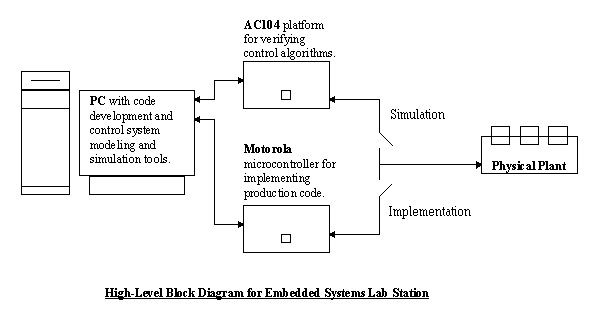
This project involves the development of a tool to facilitate
the development of real-time embedded control systems. The system will
consist of three primary subsystems. The first subsystem is a PC with software
tools for generating and compiling C and assembly code, and software for
modeling and simulating control system models in real-time. The second
subsystem is an AC104 hardware platform which will be used primarily to
verify the control algorithms within the code generated by the PC's software.
The AC104 system will control a physical system such as an engine subsystem
or an electrohydraulic implement. The third subsystem is a Motorola microcontroller
that will be used to test the production code. The Motorola microcontroller
will be running a Real-Time Operating System (RTOS).
The modes of operation for this system include a simulation
mode and a production mode. The simulation mode will involve creation
of control block diagrams that will be converted to C code through the
use of PC software. The code will then be downloaded and run on the
AC104 to evaluate the code efficiency in operating the plant. When
the simulation has generated acceptable plant control, the system can be
switched to the production mode. The production mode will consist of the
finalized simulation C code being downloaded to the Motorola microcontroller.
The microcontroller will then be controlling the plant and the microcontroller
efficiency can be evaluated. If necessary, the production code can
then be hand-tailored to meet required specifications.
The high-level system block diagram as well as the subsystem
block diagrams are shown below. The inputs and outputs of each subsystem
are located next to the corresponding block diagram.